|
|
|
Categories
|
|
Information
|
|
Featured Product
|
|
|
 |
|
|
There are currently no product reviews.
 ;
This manual is very useful because it presents the technical specifications of the cd player, including the manufacturer of the reader, this helps if you need to replace it. It also displays the settings and layout of the circuit.
;
Manual was a good representation of service infomation for the EWV404. It worked well for my repair.
 ;
Great quality copy, right what I was looking for, all I need to fix my radio.
Thanks
;
I BOUGHT A PAIR OF INFINITY VINTAGE SPEAKERS THAT REQUIRED TO BE REPAIRED AND THE ELECTRONIC TECHNICIAN ASKED ME FOR THE SERVICE MANUAL.
I TRIED TO GET IT AT THE MANUFACTURER'S SITE WITH NO SUCCESS, SO I STARTED TO LOOK FOR IT IN THE WEB FOR A LONG TIME, UNTIL I FOUND THE SERVICE MANUAL IN THIS EXCELLENT SITE "OWNER'S MANUAL.COM".
NOW I HAVE MY SPEAKERS WORKING AND ENJOYING THE MUSIC I LIKE.
THANKS TO "OWNER`S MANUAL.COM" I RECOMMEND THIS SITE TO EVERYONE.
;
Very quick response. Very good and accurate print quality of the scanned document.
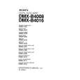
Technical Manual
MCC-1II
EXPLODED VIEW
1 17 2
3 4 5 15 10 6 18 7 11 16 8
MCC-1II Cabinet � Not for Sale
4 14 12 13
ITEM NO. DESCRIPTION 1. Front Grille (platinum) (charcoal) 2. Left Aluminum Plate 3. Grommet (platinum) (charcoal) 4. Screw 5. Baffle 6. Woofer 7. Screw 8. Left Front Pad ITEM NO. DESCRIPTION 9. Rear Cabinet (platinum) (charcoal) 10. Tweeter 11. Crossover 12. Right (Red) Terminal 13. Left (Black) Terminal 14. Back Rubber Pad 15. Screw 16. Screw 17. Right Aluminum Plate 18. Right Rubber Pad
QTY. PART NO. 1 244-040-00253W 1 244-040-00253B 1 Not For Sale 7 327-010-00112W 7 327-010-00112B 11 352-AM04020D603 1 Not For Sale 2 10PR80BZR-DW01 8 351-LM04006A565 1 320-RUB-00182
QTY. PART NO. 1 Not for Sale 1 Not for Sale 1 60DA20AD-DT01 1 013-7500-00752 1 215-000-00792 1 215-000-00793 1 320-RUB-00183 2 352-CM03010D593 4 352-FM04014D602 1 Not For Sale 1 320-RUB-00189
TO SERVICE THE MCC-1II 1. Remove the grille. 2. Remove the (7) exposed rubber grille retainers; this can be accomplished by carefully pulling them out of their cavities with long-nosed pliers or similar tool. 3. Remove the (7) Phillips screws underneath, that are now exposed. 4. Remove the (4) additional screws in their respective cavities at the rear of the housing. 5. Carefully lift the front baffle, with drivers attached, off the cabinet.
Infinity Systems, 250 Crossways Park Drive, Woodbury, New York 11797
Rev2
3/2005 6/04
MCC-1II
|
|
|
> |
|